

Choosing the right pore size in a hydrophobic PTFE filter directly determines filtration efficiency. Researchers have shown that smaller pores, such as 0.22 μm, can prevent fine particles from passing through and protect sensitive laboratory equipment. However, smaller pores may also increase analyte loss due to adsorption. Larger pores, like 0.45 μm, reduce adsorption losses but may fail to block tiny contaminants. The hollow fiber spinning machine and hollow fiber spinneret play a key role in engineering precise pore structures. Users must balance these factors to match filter performance with specific application needs.
Aspect 0.22 μm Hydrophobic PTFE Filter 0.45 μm Hydrophobic PTFE Filter Adsorption Loss Higher Lower Particle Retention Better Less Effective Instrument Protection Excellent May Allow Blockage
Key Takeaways
- Choosing the right pore size in hydrophobic PTFE filter balances filtration efficiency and flow rate to meet specific needs.
- Smaller pores capture finer particles but reduce flow, while larger pores allow faster flow but may miss tiny contaminants.
- The hollow fiber spinning machine shapes pore size and membrane structure, ensuring consistent filter performance.
- PTFE membranes resist harsh chemicals and high temperatures, making them ideal for demanding filtration tasks.
- Regular testing and maintenance help keep filters effective and extend their lifespan in various applications.
Hydrophobic PTFE Filter Basics
PTFE Material Properties
PTFE membranes stand out in filtration due to their unique molecular structure. The repeating -CF₂-CF₂- units create a surface with extremely low surface free energy, measured at just 18.6 mJ/m². This low energy results from strong carbon-fluorine bonds, which also provide high bond energy and exceptional chemical inertness. PTFE membranes resist degradation, even in harsh chemical environments. Their thermal stability allows operation at temperatures up to 260°C. These membranes also show impressive wear resistance, low friction, and corrosion resistance. The hollow fiber spinning machine and hollow fiber spinneret enable precise control over membrane formation, ensuring consistent pore structure and reliable filter performance. These combined properties make PTFE membranes a preferred choice for demanding filtration applications.
Hydrophobicity Explained
The hydrophobic nature of PTFE membranes comes from their non-polar surface, which repels water. The strong carbon-fluorine bonds create a high water contact angle, often between 110° and 140°. Water droplets bead up and do not penetrate the membrane easily. This hydrophobic membrane behavior prevents liquid water from passing through unless subjected to high pressure. In filtration, this property stops aqueous solutions from entering the pores, allowing only gases to pass. The hydrophobic PTFE filter excels in gas filtration by blocking water vapor condensation and reducing pore blockage. The membrane’s pore size and structure, shaped during manufacturing with tools like the hollow fiber spinning machine, further influence filtration efficiency and permeability.
Tip: The hydrophobic membrane property also enables waterproof yet breathable fabrics, allowing water vapor to escape while blocking liquid water.
Common Uses
Hydrophobic PTFE filter serves a wide range of industrial and laboratory applications. The table below highlights key uses and performance metrics:
| Application Area | Description |
|---|---|
| Venting | Used in electrical enclosures, container venting, diagnostics, medical devices, EV battery vents. Enables pressure equalization and protection. |
| Filtration | Sterilization container filters combine venting and filtration to prevent cross-contamination, providing bacterial barriers during storage. |
| UV Disinfection | PTFE membranes used for their high reflectivity to evenly distribute UVC energy for pathogen deactivation. |
PTFE membranes deliver filtration efficiency greater than 99.99% and maintain high chemical resistance. Their robust design withstands repeated sterilization and harsh industrial use. Hydrophobic PTFE filter also supports applications in electronics, automotive, and medical fields, where reliable filtration and venting are critical.
Pore Structure in PTFE Membrane
Pore Size and Distribution
Pore size stands as a critical factor in the performance of ptfe membranes. Manufacturers measure filter pore size using advanced techniques such as Scanning Electron Microscopy (SEM), Transmission Electron Microscopy (TEM), and bubble point testing. These methods provide detailed insight into the membrane structure, revealing pore diameters that typically range from 0.05 to 10 micrometers. Commercial hydrophobic ptfe membranes often feature nominal pore sizes like 0.2, 0.45, 1, 3, 5, and 10 microns, with the most common centered around 0.45 micrometers.
The distribution of pores within a ptfe porous membrane is not perfectly uniform. Instead, membranes display a statistical distribution of pore sizes, which influences both filtration consistency and overall performance. For example, a membrane with a nominal pore size of 0.45 micrometers will contain a range of pore diameters above and below this value. This distribution is measured using instruments such as the Coulter Porometer II and modified bubble point methods. The table below summarizes key parameters for commercial ptfe membranes:
| Parameter | PTFE Membranes (Commercial) | Notes and Impact on Filtration Consistency |
|---|---|---|
| Nominal pore size | ~0.45 µm | Average value, not absolute; measured by porometry |
| Pore size distribution method | Coulter Porometer II, bubble point | Confirms statistical distribution |
| Membrane thickness | ~80 µm | Affects flux and mechanical strength |
| Flux (water) | 2.31–5.52 kg/h/m² | Higher with larger pores and porosity |
| Hydrophobicity (contact angle) | 32–36° | Surface roughness affects fouling |
| Fouling tendency | Higher with larger pores and polar surface energy | Impacts long-term filtration consistency |
| Filtration performance | Lactose retention 92–99% | High selectivity despite distribution |
A well-controlled pore size and distribution in a porous ptfe membrane ensures reliable filtration, balancing high flux with consistent contaminant retention.
Impacton Filtration Efficiency
Filtration efficiency in ptfe membranes depends on several interconnected factors: pore size, porosity, thickness, and distribution. Smaller pores, such as those found in a 0.22 micrometer membrane, deliver superior contaminant removal—often exceeding 99% efficiency. However, these fine pores restrict flow, resulting in lower flux and higher pressure drop across the filter. Larger pores, like 0.45 micrometers, increase flux but may allow smaller contaminants to pass through, reducing filtration efficiency.
Porosity also plays a significant role. High porosity, typically between 85% and 93% in porous ptfe, increases the available surface area for filtration. This enhancement boosts flux and helps resist fouling and wetting. Membrane thickness further influences performance. Thinner membranes promote higher permeability and greater flux, while thicker membranes may improve contaminant rejection and reduce heat loss.
Uniform pore distribution across the membrane surface ensures stable filtration efficiency and consistent performance. Non-uniformity can lead to localized areas of reduced contaminant removal or increased fouling. Hydrophobicity, measured by the water contact angle and liquid entry pressure, provides additional protection against wetting, especially in hydrophobic ptfe membranes. These membranes often achieve liquid entry pressures above 5 bars, outperforming alternatives like PVDF.
Experimental data confirms these relationships. For example, filters with smaller effective pore sizes and lower permeability exhibit higher pressure drops at the same face velocity. The membrane layer, with its fine pore structure, contributes most to both filtration efficiency and flow resistance. The table below illustrates how membrane properties affect flux and contaminant removal:
| Membrane Property | Effect on Flux and Contaminant Removal Efficiency |
|---|---|
| Pore Size | Larger pores increase flux but reduce contaminant rejection; smaller pores enhance removal efficiency but limit flux. |
| Porosity | High porosity increases flux and fouling resistance. |
| Thickness | Thinner membranes improve permeability; thicker membranes may enhance contaminant rejection. |
| Pore Distribution | Uniform distribution improves flux and stability. |
| Hydrophobicity & LEP | High hydrophobicity and LEP improve wetting resistance and contaminant removal. |
Note: The pressure drop across the membrane layer is much higher than that of the fibrous layer. Fine pore structure in the membrane increases flow resistance, making it the main contributor to both filtration efficiency and pressure drop.
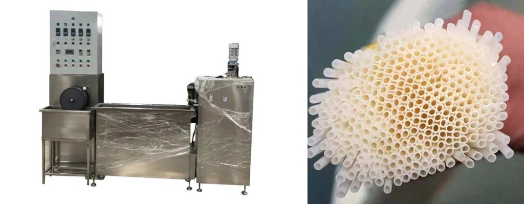
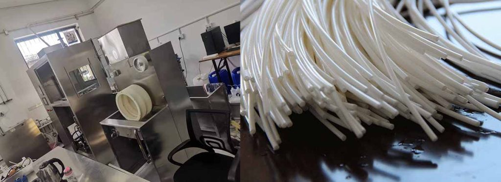
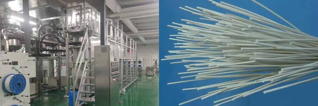
Role of Hollow Fiber Spinning Machine
The hollow fiber spinning machine and hollow fiber spinneret play a pivotal role in engineering the pore structure of ptfe membranes. During fabrication, the spinning process allows precise control over stretching ratios, temperature, and extrusion speed. Adjusting these parameters tailors the pore size, porosity, and surface roughness of the resulting porous ptfe fibers.
A lower stretching temperature and a moderate stretching ratio, such as 30%, yield a concentrated pore size distribution. Manufacturers can adjust the pore size range from approximately 0.17 to 0.55 micrometers by fine-tuning the spinning conditions. Higher stretching ratios increase porosity, which enhances membrane flux and permeability. However, excessive stretching can thin the membrane, slightly reduce tensile strength, and decrease the water contact angle due to smoother surfaces.
The hollow fiber spinning machine also impacts mechanical stability and functional performance. For example, membranes with optimal stretching ratios achieve high liquid entry pressures (up to 600 kPa), ensuring excellent wetting resistance. These membranes maintain adequate mechanical strength, even as porosity and flux increase. In applications such as membrane distillation and CO2 absorption, the ability to engineer pore structure with the hollow fiber spinneret results in superior separation performance and long-term durability.
The hollow fiber spinning machine enables manufacturers to customize ptfe porous membrane properties for specific filtration needs, optimizing the balance between filtration efficiency, flux, and mechanical stability.
Efficiency Factors in Hydrophobic PTFE Filter
Particle Retention
Hydrophobic PTFE filter achieves high filtration efficiency by capturing a wide range of particles. The membrane structure, engineered with precision using a hollow fiber spinning machine and hollow fiber spinneret, determines the minimum particle size retained. Studies show that these filters can effectively trap nanoparticles as small as 20 nm. The retention mechanism depends on the relationship between particle diameter and pore size. When the particle is larger than the pore, sieving occurs. For smaller particles, diffusion and electrostatic interactions play a role. The table below summarizes retention data:
| Particle Type | Particle Sizes Tested (nm) | Membrane Type | Filtration Mechanisms | Retention Notes |
|---|---|---|---|---|
| Silver nanoparticles | 20, 40, 100 | ePTFE | Sieving, diffusion, electrostatic | Reliable retention down to 20 nm; depends on particle-to-pore size ratio |
| Polystyrene latex (PSL) | 50, 70, 100, 150, 200 | ePTFE | Same as above | Efficiency influenced by particle size, charge, and liquid properties |
This high performance in particle retention supports applications demanding absolute sterility, such as biopharmaceutical production and laboratory quality control. Hydrophobic membrane filters maintain purity and effective filtration, ensuring product quality and safety.
Flow Rate and Pressure
The flow rate and pressure requirements of hydrophobic PTFE membrane depend on pore size, porosity, and membrane structure. Membranes with higher porosity and lower tortuosity, often produced by advanced hollow fiber spinning machines, deliver faster flow rates and lower resistance. Smaller pores increase the liquid entry pressure, which stabilizes the gas/liquid interface and improves wetting resistance. However, higher filtration efficiency often requires higher operational pressure. The table below compares membrane properties:
| Membrane Type | Porosity (%) | Tortuosity | Water Flux (kg/h/m²) | Structural Resistance (µm) |
|---|---|---|---|---|
| Nanofiber PTFE | ~73 | Low | High | 102-148 |
| Commercial PTFE | ~33 | High | Moderate | 1256 |
Smaller pore sizes and optimized structures enhance separation efficiency but may require increased pressure to maintain flow. Operators must balance filtration efficiency with flow rate to achieve sterility and maintain process productivity.
Chemical Resistance
PTFE membranes stand out for their exceptional chemical resistance. The hydrophobic membrane structure resists strong acids, bases, and organic solvents, making it ideal for aggressive filtration tasks in biopharmaceutical and industrial settings. Unlike nylon or cellulose acetate, PTFE maintains integrity and filtration efficiency across a wide pH and temperature range. The chart below compares chemical resistance among common filter materials:
PTFE filters require pre-wetting with alcohols for aqueous filtration, but their durability ensures consistent separation efficiency and sterility. Plasma treatment can further enhance hydrophobicity, increasing the water contact angle and reducing particulate adhesion. This modification helps maintain filtration efficiency and purity, even under challenging conditions. PTFE’s chemical resistance and high performance make it the preferred choice for quality control and demanding filtration applications.
Selecting Pore Size for Applications
Air and Gas Filtration
Air and gas filtration represent some of the most common applications of porous ptfe membranes. These membranes provide a hydrophobic barrier that prevents water and aerosols from passing through, while allowing gases to flow freely. In sterile venting, compressed air filtration, and gas sampling, the filter pore size plays a critical role in determining both efficiency and throughput.
For air and gas filtration, manufacturers typically select pore sizes between 0.2 µm and 1.0 µm. A 0.2 µm membrane, often produced using a hollow fiber spinning machine and hollow fiber spinneret, serves as a sterilizing-grade filter for critical applications. This controlled pore size ensures reliable retention of airborne bacteria and fine particulates. Larger pore sizes, such as 0.45 µm or 1.0 µm, are suitable for less demanding tasks like dust removal or pre-filtration, where higher flow rates are required.
The following table summarizes typical pore sizes and their performance characteristics for air and gas filtration:
| Application | Typical Pore Size (µm) | Filtration Purpose | Notes |
|---|---|---|---|
| Sterile venting | 0.2 | Bacteria and particle retention | Used in bioreactors, fermenters |
| Compressed air filtration | 0.2 – 0.45 | Remove fine particulates | Protects sensitive equipment |
| Gas sampling | 0.45 – 1.0 | Remove dust, aerosols | High flow, lower retention |
Porous ptfe membranes maintain high chemical resistance and hydrophobicity, making them ideal for aggressive or humid gas streams. The membrane structure, engineered with a hollow fiber spinning machine, ensures consistent performance across a range of operating conditions.
Liquid And Chemical Filtration
Liquid and chemical filtration demand precise control over membrane properties. In these applications, the selection of filter pore size directly impacts both contaminant retention and process efficiency. PTFE membranes, known for their chemical inertness and hydrophobic nature, excel in filtering aggressive solvents, acids, and bases.
Manufacturers offer a range of pore sizes for liquid and chemical filtration, typically from 0.10 µm to 1.00 µm. The choice depends on the required level of sterility and the size of contaminants to be removed. For sterilizing-grade filters, a 0.2 µm absolute pore size is standard, ensuring the removal of bacteria such as Brevundimonas diminuta. Larger pore sizes, like 0.45 µm or 1.0 µm, are used for clarification or pre-filtration steps, where the goal is to remove larger particulates and protect downstream membranes.
The table below details key parameters for hydrophobic PTFE membrane used in liquid and chemical filtration:
| Pore Size (µm) | Bubble Point (MPa) | Flow Rate Water (mL/min/cm²) | Porosity (%) |
|---|---|---|---|
| 0.10 | ≥0.38 (≥55.1 psi) | 14 | 71 |
| 0.20 | ≥0.24 (≥34.8 psi) | 21 | 71 |
| 0.50 | ≥0.14 (≥20.3 psi) | 39 | 79 |
| 1.00 | ≥0.083 (≥12.0 psi) | 73 | 83 |
The bubble point test, which measures the minimum pressure required to force air through a wetted membrane, provides a reliable method for verifying membrane integrity. As the pore size increases, the bubble point decreases, and the flow rate rises. This relationship allows users to select the optimal balance between filtration efficiency and throughput.
Porous ptfe membranes with high porosity, typically between 71% and 83%, deliver excellent flow rates while maintaining strong contaminant retention. The hollow fiber spinning machine and hollow fiber spinneret enable precise adjustment of these parameters, supporting a wide range of applications of porous ptfe membranes in chemical processing, pharmaceutical production, and laboratory analysis.
Practical Selection Tips
Selecting the right filter pore size for a specific application requires careful consideration of several factors. The following guidelines help users match porous ptfe membranes to their filtration needs:
- Choose a 0.2 µm absolute pore size for sterilizing-grade filtration, especially in pharmaceutical and bioprocessing environments. This ensures reliable removal of bacteria and compliance with industry standards.
- Use larger pore sizes, such as 0.45 µm or 1.0 µm, for pre-filtration or clarification steps. These membranes remove larger particulates and extend the life of finer downstream filters.
- Assess the chemical compatibility of the membrane with the process fluid. PTFE membranes resist a wide range of chemicals, making them suitable for oils, solvents, and aggressive reagents.
- Balance filtration efficiency and flow rate. Finer pores increase contaminant retention but reduce throughput. Coarser pores improve flow but may allow smaller contaminants to pass.
- Consider multilayer filtration systems. Combining membranes with different pore sizes can enhance overall efficiency by 20%–30% and prevent clogging.
- Pilot testing and expert consultation can optimize membrane selection for unique process requirements.
Tip: Always verify membrane integrity using bubble point or challenge tests before critical filtration steps.
Industry standards recommend a 5-micron pore size as a compromise between efficiency and flow rate for general filtration. However, for hydrophobic PTFE filters, users should tailor the selection to the specific application, contaminant size, and process demands. Pleated cartridge designs offer higher surface area and flow capacity, though at a higher cost.
Porous ptfe membranes, engineered with a controlled pore size using advanced manufacturing methods like the hollow fiber spinning machine, provide unmatched versatility and reliability. By understanding the trade-offs and application requirements, users can maximize the performance and lifespan of their filtration systems.
PTFE Porous Membrane vs. Expanded Types
Manufacturing Differences
Manufacturers use distinct processes to create PTFE porous membrane and expanded PTFE. Porous PTFE sheets result from additive sublimation from a PTFE billet, which leaves behind irregular voids. In contrast, expanded PTFE membranes form through mechanical stretching, producing a uniform microporous structure. The hollow fiber spinning machine and hollow fiber spinneret allow precise control over the pore structure in both types, but the resulting characteristics differ significantly.
| Feature | Porous PTFE Sheets | Expanded PTFE Membranes (ePTFE) |
|---|---|---|
| Manufacturing Process | Additive sublimation from PTFE billet, creating irregular voids | Mechanical stretching of PTFE, producing uniform microporous structure |
| Pore Structure | Larger, irregular pores due to voids left by additives | Consistent, sub-micron pores with uniform size and interconnectivity |
| Effect on Pore Size | Less precise control, suitable for coarse filtration | Precisely controlled pore size, ideal for selective gas permeability and advanced filtration |
Porous PTFE sheets are rigid and have limited compressibility, reflecting their larger, irregular pores. Expanded PTFE membranes are soft, flexible, and highly compressible, which matches their fine, uniform microporous structure.
Efficiency Comparison
The efficiency of PTFE porous membrane and expanded PTFE depends on their structure and thickness. Porous PTFE membranes, often fabricated by electrospinning, are thicker and tougher. Their interconnected fibrous network provides improved handling and durability. Expanded PTFE membranes, with their node-fibril structure, offer high gas permeability and particle retention. However, they may show a wider pore size distribution and lower porosity at small thicknesses.
Laboratory tests reveal that expanded PTFE membranes can experience rapid increases in pressure drop during extended use, indicating possible pore structure degradation. In contrast, embedded PTFE membranes maintain a stable pressure drop and consistent filtration efficiency, demonstrating superior operational stability. These characteristics make PTFE porous membrane a strong choice for high-performance separation membranes and membrane distillation technology.
Application Suitability
Porous PTFE membranes excel in barrier functions, especially in guided bone and tissue regeneration procedures. Their dense structure and small pore size protect bone grafts from bacterial and soft tissue invasion. Surface texturing can enhance stability by promoting cell adhesion. These membranes also perform well in filtration and liquid/air separation, making them valuable as high-performance separation membranes.
Expanded PTFE membranes are ideal for biomedical applications such as vascular stent coatings. Their flexibility, chemical inertness, and biocompatibility support use in vascular disease treatments. Manufacturers can tune porosity and mechanical properties through stretching, pore-forming, and sintering. Functionalization further improves blood compatibility and reduces vascular damage, expanding the applications of eptfe membranes in surgical implants and vascular treatments.
Note: The choice between porous PTFE and expanded PTFE depends on the required mechanical properties, filtration precision, and application environment. The hollow fiber spinning machine and hollow fiber spinneret enable customization for both types, supporting a wide range of industrial and biomedical uses.
Summary and Key Takeaways
Matching Filter to Application
Selecting the right hydrophobic PTFE filter ensures optimal filtration, sterility, and product quality in critical industries. Each application, from biopharmaceutical manufacturing to electronics, demands careful evaluation of filter properties. Users should consider the following factors when matching filter characteristics to their process:
- Identify the specific material and performance requirements based on what needs filtration.
- Evaluate the chemical and biological makeup of the stream to avoid compatibility issues.
- Determine the necessary pore size and removal efficiency, including whether absolute or nominal ratings are needed for absolute sterility.
- Assess the expected particle load and potential for fouling.
- Define the required flow rate and batch size to ensure the filter matches process throughput.
- Consider regulatory and validation needs, such as bacteria retention, FDA or EU food contact, and endotoxin control for biological drug product manufacturing.
- Choose the appropriate filter configuration, such as cartridge or capsule, and ensure correct end fittings.
- Plan for system and filter sanitization methods, including hot water, steam, or chemical cleaning.
- For aggressive solvents, select PTFE membranes due to their chemical resistance.
- For gas filtration or venting, hydrophobic PTFE membranes are preferred.
- Consult with vendor applications engineering for testing and validation to confirm filter suitability.
The hollow fiber spinning machine and hollow fiber spinneret enable precise engineering of membrane properties, supporting these diverse requirements.
Actionable Steps
To ensure correct selection and use of hydrophobic PTFE filter, users can follow these steps:
- Assess chemical compatibility to confirm the membrane resists process liquids.
- Select the appropriate pore size for the desired filtration goal, such as 0.2 µm for sterilization.
- Choose the correct cartridge size and configuration based on flow rate, temperature, and pressure.
- Perform routine maintenance, including flushing with clean water or compatible solvents, to prevent fouling.
- Conduct integrity testing, such as bubble-point or diffusion tests, after installation and cleaning cycles.
- Monitor differential pressure to detect clogging and determine replacement timing.
- Use new O-rings during reassembly and follow proper sanitization protocols, such as steam-in-place at 121°C.
- Apply application-specific recommendations, such as using hydrophobic PTFE membrane for aggressive solvents or air filtration.
- Understand that membrane lifespan depends on feed quality, operating pressure, and temperature, and plan replacements accordingly.
Hydrophobic PTFE membrane, especially those produced with a hollow fiber spinning machine and hollow fiber spinneret, offers strong chemical resistance and maintain sterility in demanding environments. Their use in biopharmaceutical and other industries supports high purity and reliable filtration, protecting both product and process.
Conclusion
Selecting the right hydrophobic ptfe filter depends on understanding how pore size and structure impact efficiency.
- Pore size and microstructure, shaped by the hollow fiber spinning machine and hollow fiber spinneret, directly affect air permeability and filtration performance.
- Smaller pores improve retention but may reduce flow, while larger pores increase flux at the expense of separation efficiency.
- PTFE membranes offer strong chemical compatibility, making them ideal for challenging environments.
Professionals should balance efficiency, flow rate, and chemical resistance, following best practices to ensure optimal filter selection for each application.